about us
News Center
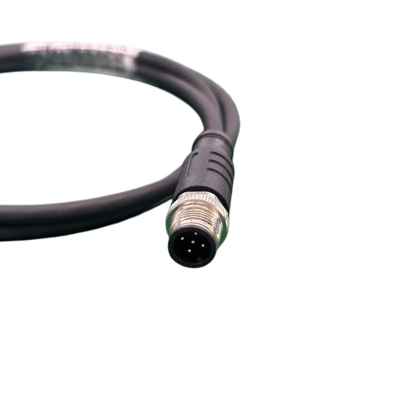
Your current location:Home - About us - News centerPin count follows the protocol. A 5-pin DeviceNet or CAN BUS branch is a trunk-and-drop network on five conductors, so a five-contact A-coded distributor matches it directly: one input feeding three outputs, each carrying the same five signals. Moving to four contacts drops the drain path and leaves the shield to find another route. Moving to eight adds three contacts your cable cannot use unless the drawing assigns them a job. Eight- and twelve-position layouts come into their own when a single drop collects several sensor channels, or when bus data and 24 V auxiliary power share one shell—the point where the layout starts to behave like a hybrid connector. For these mixed layouts, involve the hybrid connector manufacturer early and ask the hybrid connector supplier for a written pinout rather than relying on the housing or contact count alone. Two- and three-position bodies stay useful for a single sensor or a power-only branch. Pin count also fixes the mating cordsets, the field-attachable plugs on your spares shelf, and the re-pin work during commissioning. Choosing a higher count for expansion only pays off if the extra contacts are defined now; otherwise each spare position becomes an invitation to guess. The distributor adds branch points, but the physical-layer rules for stub length and total bus length still come from the protocol itself. NXP's CAN physical-layer application note is a useful reminder that reflections and bit timing, not the splitter body, set those limits. Require the manufacturer's internal pinout and any termination arrangement in writing with the order, so the contact count you approve is the one that arrives.